●Working power supply: AC220V 50Hz±5% ●Working environment: ambient temperature 40; humidity 85(without dew);without strong magnetic ifeld;without strong vibration ●Input signal:4-20mA linear current (0-10mA, 0~10V, 1~5V, please give indications when ordering goods) ●Output capacity: Drive SCR (trigger pulse 3V/200mA, 50μs)
Use method
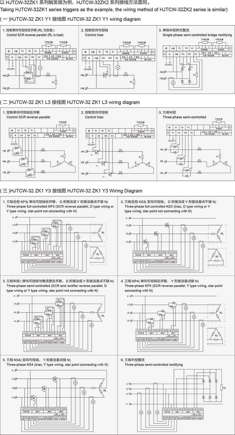
1、Automatic outoput: When the "common-automatic" terminal is short-circuited, the trigger output volume can be controlled through inputting 4-20mA signal from the "input signal +,-" terminal. 2、Manual output: When the "common-automatic" terminal is short-cicuited, the trigger output volume can be controlled through the "manual adjustment (1K potentiometer)" 3、Curent limit: When the current limit function is used, for TCW-32ZKY1, the current transformer signals in the main circuit shall be introduced to the “A1-A2” terminal; for TCW-32ZKY3, the current transformer signals in the three-phase main circuit shall be respectively introduced to “A1-A2,A3-A4,A5-A6” terminals. And connect with the "current limit (1K potentiometer)" externally to adjust the current limit value through the potentiometer. In order not to influence the adjustment and output of the main control meter, when the current limit function is used, the current limit value is generally set near the rated current of load. In addition, to reliabley use the over current protection function, it is also necessary to set the current limit value near the rated current of load.